-
What happened?
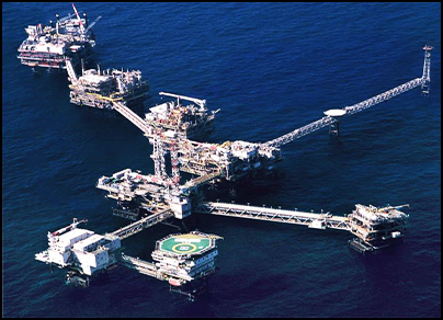
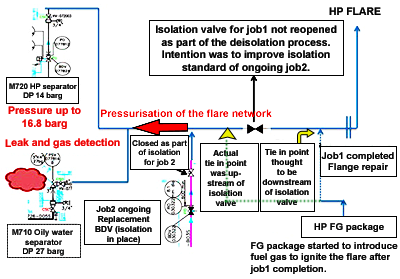
On an oil platform complex, production was shut down to repair a laminated section of a flow element’s (FE) flange connected to high pressure (HP) flare.
The flare header was under nitrogen sweeping prior to the isolation to allow for break of containment for spading.
The process isolation included a valve (V1) on the flare header at connection with HP flare header (job 1).
In parallel to the flange repair job, a stuck closed blow down valve (BDV), also connected to the HP flare network, was being replaced (job 2) using an independent isolation plan.
After completing the flange repair, the team left valve V1 isolated to have an additional barrier for BDV side isolation.
The following then happened:
The team lit the flare and the fuel gas (FG) package was pressurised. The flow from the FG package was diverted to the flare header.
Two pressure alarms sounded and a gas detection leak (10% LEL) was discovered (M710 area – see diagram).
The offshore emergency response team (ERT) was mobilised.
The distributed control system (DCS) operator stopped the fuel gas arriving to the flare header and initiated emergency shut down (ESD).
A second gas detector reached 10% LEL.
The ERT found the source of the pressure build up and opened flare isolation valve V1.
All areas were quickly depressurised.
No personnel were injured, but the incident had catastrophic potential. The pressure safety valves (PSVs) suffered minor damages.

-
Why did it happen?
Instead of lighting the flare by starting the wells, the production team decided to use an alternate way of lighting the flare by using the gas from fuel gas (FG) package which operates at 24 barg. They assumed that the FG injection point was located downstream of V1.
Using the HP FG and leaving the valve V1 closed resulted in the pressurisation of part of the HP flare network above its design pressure.
A damaged bellow on the PSV of the M710 separator and an opened end on the same PSV’s bonnet resulted in the release of gas to atmosphere while the flare network was pressurised.
The team did not operate within correct safe working procedures:
- No start up procedure
- No management of change process was applied to the change in commonly used start up sequence.
- Isolations were closed without following correct procedure.
- PSFs were not set up with leak detection devices.
- The team felt an urgency to restart the plant quickly to minimise production shortfalls.

-
What did they learn?
Perform line walks on the flare network to identify all flare valves and review flare valve management.
Perform a site survey and set up an action plan for open end PSVs.
Ensure proper resource planning is carried out for all tasks.
All personnel should be familiar with the procedures, field instructions and ‘stop work’ procedure.
Reinforce piping and instrumentation diagrams (P&IDs) mark-up management for process isolation (anticipation, preparation, distribution, use, revision etc.).
Review the affiliate process isolation procedure.

-
Ask yourself or your crew
A change of method for one task (lighting the flare) had a large impact on the overall incident – how could that happen in anything you undertake today?
When introducing fuel gas to ignite the flare, how can you check the correct location of the injection point?
When several jobs are done simultaneously, how can you ensure that what you do does not affect other teams’ work and vice versa?
Have you ever felt under time pressure to complete a task? How has this impacted your work decisions?
What should you do if you ever noticed anyone ‘cut corners’ on a job?

Add to homescreen
Content name
Select existing category:
Content name
New collection
Edit collection
What happened?
On an oil platform complex, production was shut down to repair a laminated section of a flow element’s (FE) flange connected to high pressure (HP) flare.
The flare header was under nitrogen sweeping prior to the isolation to allow for break of containment for spading.
The process isolation included a valve (V1) on the flare header at connection with HP flare header (job 1).
In parallel to the flange repair job, a stuck closed blow down valve (BDV), also connected to the HP flare network, was being replaced (job 2) using an independent isolation plan.
After completing the flange repair, the team left valve V1 isolated to have an additional barrier for BDV side isolation.
The following then happened:
The team lit the flare and the fuel gas (FG) package was pressurised. The flow from the FG package was diverted to the flare header.
Two pressure alarms sounded and a gas detection leak (10% LEL) was discovered (M710 area – see diagram).
The offshore emergency response team (ERT) was mobilised.
The distributed control system (DCS) operator stopped the fuel gas arriving to the flare header and initiated emergency shut down (ESD).
A second gas detector reached 10% LEL.
The ERT found the source of the pressure build up and opened flare isolation valve V1.
All areas were quickly depressurised.
No personnel were injured, but the incident had catastrophic potential. The pressure safety valves (PSVs) suffered minor damages.

Why did it happen?
Instead of lighting the flare by starting the wells, the production team decided to use an alternate way of lighting the flare by using the gas from fuel gas (FG) package which operates at 24 barg. They assumed that the FG injection point was located downstream of V1.
Using the HP FG and leaving the valve V1 closed resulted in the pressurisation of part of the HP flare network above its design pressure.
A damaged bellow on the PSV of the M710 separator and an opened end on the same PSV’s bonnet resulted in the release of gas to atmosphere while the flare network was pressurised.
The team did not operate within correct safe working procedures:
- No start up procedure
- No management of change process was applied to the change in commonly used start up sequence.
- Isolations were closed without following correct procedure.
- PSFs were not set up with leak detection devices.
- The team felt an urgency to restart the plant quickly to minimise production shortfalls.

What did they learn?
Perform line walks on the flare network to identify all flare valves and review flare valve management.
Perform a site survey and set up an action plan for open end PSVs.
Ensure proper resource planning is carried out for all tasks.
All personnel should be familiar with the procedures, field instructions and ‘stop work’ procedure.
Reinforce piping and instrumentation diagrams (P&IDs) mark-up management for process isolation (anticipation, preparation, distribution, use, revision etc.).
Review the affiliate process isolation procedure.
Ask yourself or your crew
A change of method for one task (lighting the flare) had a large impact on the overall incident – how could that happen in anything you undertake today?
When introducing fuel gas to ignite the flare, how can you check the correct location of the injection point?
When several jobs are done simultaneously, how can you ensure that what you do does not affect other teams’ work and vice versa?
Have you ever felt under time pressure to complete a task? How has this impacted your work decisions?
What should you do if you ever noticed anyone ‘cut corners’ on a job?
A gas leak occurred on an oil platform complex during a repair of a blow down valve. No personnel were injured. The pressure safety valves (PSVs) suffered minor damages.


